Orthographic Drawing: What It Is, How to Sketch It, and When to Use It
What is an orthographic drawing, and why does it remain the standard for technical communication when more visually intuitive projection methods exist? The answer lies in what orthographic drawing does that no other drawing system achieves: it shows each face of an object at true scale without the distortion introduced by perspective or isometric projection. When you need to communicate exact dimensions across multiple surfaces of a three-dimensional object, an orthographic sketch is the most reliable tool available. Understanding this system is a fundamental skill for engineers, architects, industrial designers, and anyone working at the intersection of visual communication and physical production.
This guide explains what is an orthographic drawing and how it differs from other drawing systems, how to create an orthographic sketch using standard conventions, the specific contexts where orthographic sketches are the correct choice, and how orthogonal drawing relates to the broader orthographic drawing tradition.
What Is an Orthographic Drawing
Definition and Core Principles
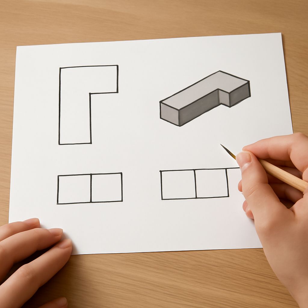
An orthographic drawing represents a three-dimensional object through a set of two-dimensional views, each showing the object as seen directly from one direction with no perspective distortion. The standard set of views includes front, side, and top views at minimum, with additional views added as needed to fully describe the object’s geometry. What is an orthographic drawing’s defining characteristic is that all parallel lines remain parallel in the drawing, and all faces appear at their true shape and size without foreshortening.
This is the fundamental difference between orthographic drawing and perspective drawing. In perspective, objects that are further away appear smaller. In an orthographic drawing, an edge that is further away appears at the same scale as one that is closer, because all projection lines are parallel rather than converging at a viewpoint. This property is what makes orthographic drawing usable for dimensional specification: you can take measurements directly from the drawing.
First-Angle vs. Third-Angle Projection
Orthographic drawing has two standard projection conventions in use worldwide. First-angle projection, standard in Europe and many other regions, places the side view to the left of the front view. Third-angle projection, standard in the United States and some other countries, places the side view to the right. An orthographic sketch should always indicate which convention it uses to prevent misreading by someone unfamiliar with the specific convention your drawing follows.
How to Create an Orthographic Sketch
Setting Up Your Views
Begin an orthographic sketch by determining which views you need to fully describe the object. A simple rectangular block needs only two views. Complex objects with features on multiple faces may need five or six. Arrange your views with consistent spacing and alignment: in third-angle projection, the top view aligns directly above the front view, and the right side view aligns directly to the right of the front view. This alignment allows you to project measurements from one view to another using horizontal and vertical guidelines.
Draw each view in orthographic drawing using thin construction lines first, capturing the visible outlines of each face. Then add hidden lines, typically drawn as dashed lines, to indicate edges that are not visible from the current viewing direction but are part of the object’s geometry. Center lines indicate axes of symmetry and centers of holes or circular features.
Dimensioning Your Orthographic Sketches
Orthographic sketches communicate dimensions through a specific system of extension lines, dimension lines, and numerical annotations. Extension lines project from the edges of the object perpendicular to the dimension being measured. Dimension lines run parallel to the measured edge with arrowheads or tick marks at each end. The numerical dimension value appears along or above the dimension line. This dimensioning system is standardized across engineering and architectural drawing to prevent ambiguity in how measurements should be read.
Orthogonal Drawing and Related Concepts
Orthogonal drawing is a term often used interchangeably with orthographic drawing, and in most practical contexts the distinction is negligible. Technically, orthogonal refers to the right-angle relationship between the projection lines and the projection plane, which is the defining geometric property of both systems. In everyday usage, orthographic drawing and orthogonal drawing describe the same type of multi-view technical illustration.
Understanding orthographic drawing as a system distinct from axonometric methods like isometric drawing clarifies when to use each. Isometric drawing shows a three-dimensional view that’s visually intuitive but dimensionally distorted. Orthographic drawing sacrifices visual intuitiveness for dimensional accuracy. Use orthographic sketches when the information must be measured and built from. Use isometric or perspective drawing when the goal is communicating what something looks like rather than how to produce it.
Bottom line: An orthographic drawing is the standard for technical and engineering communication precisely because it preserves true scale across all faces simultaneously. Learning to create and read orthographic sketches is a foundational skill for anyone who works with technical documentation, product design, or architectural drawing, and orthogonal drawing conventions are worth mastering early in any technical design education.